Implicit modeling custom screws and nuts using libfive
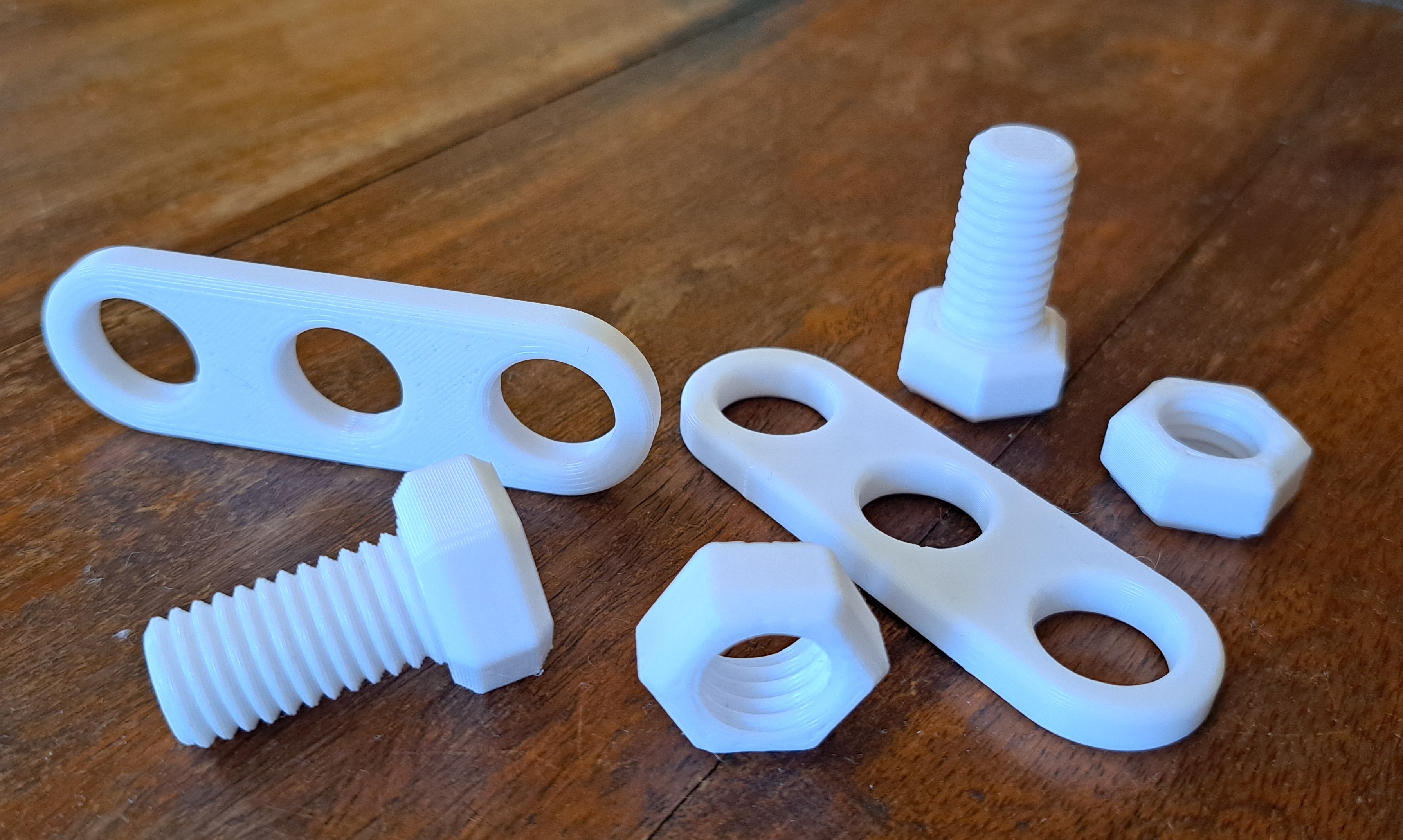
I wanted to 3D print a custom thread on a plastic screw (for a simple toy application). Using my usual CAD of choice, Fusion 360, this turned out to be surprisingly difficult: The only supported way to get custom threads seems to be to edit an XML file inside the fusion distribution. After that your design will not work on a different computer without the same modification. You can make helixes with triangular shape but only with 60 degree angle on the triangle; modeling a custom thread seems next to impossible (if you do know how, let me know and I’ll add a link here).
This seemed like a good excuse to use generative design (the programming kind, not the AI kind :).
I’ve been looking at implicit modeling for a long time. Using use marching cubes in some projects, playing around with doing it in Jax in some others. It’s mostly been a “meh” experience - too slow, too imprecise &c. But this time it finally clicked: libfive. I’ve looked at it before but had some issue or other compiling it and was generally averse to a tool with a new language (guile, a scheme lisp dialect). Now, with homebrew on a macbook, compilation went without a hitch. There is even a python binding now but just for kicks, I decided to use guile, their default language. (If I start using it in anger, it’s probably going to be python all the way)
Hex nut
A simple hex nut blank is easy:
;; Hex nut without hole, from -h to 0
(define-shape (hex x y z)
  (let ((z-inside (- (abs (+ z (/ nut-height 2))) (/ nut-height 2))))
    (max
     z-inside
     (polygon (+ (* nut-corner-radius 0.5)
                (min 0 (- -2 z-inside))) ; chamfer
              6))))
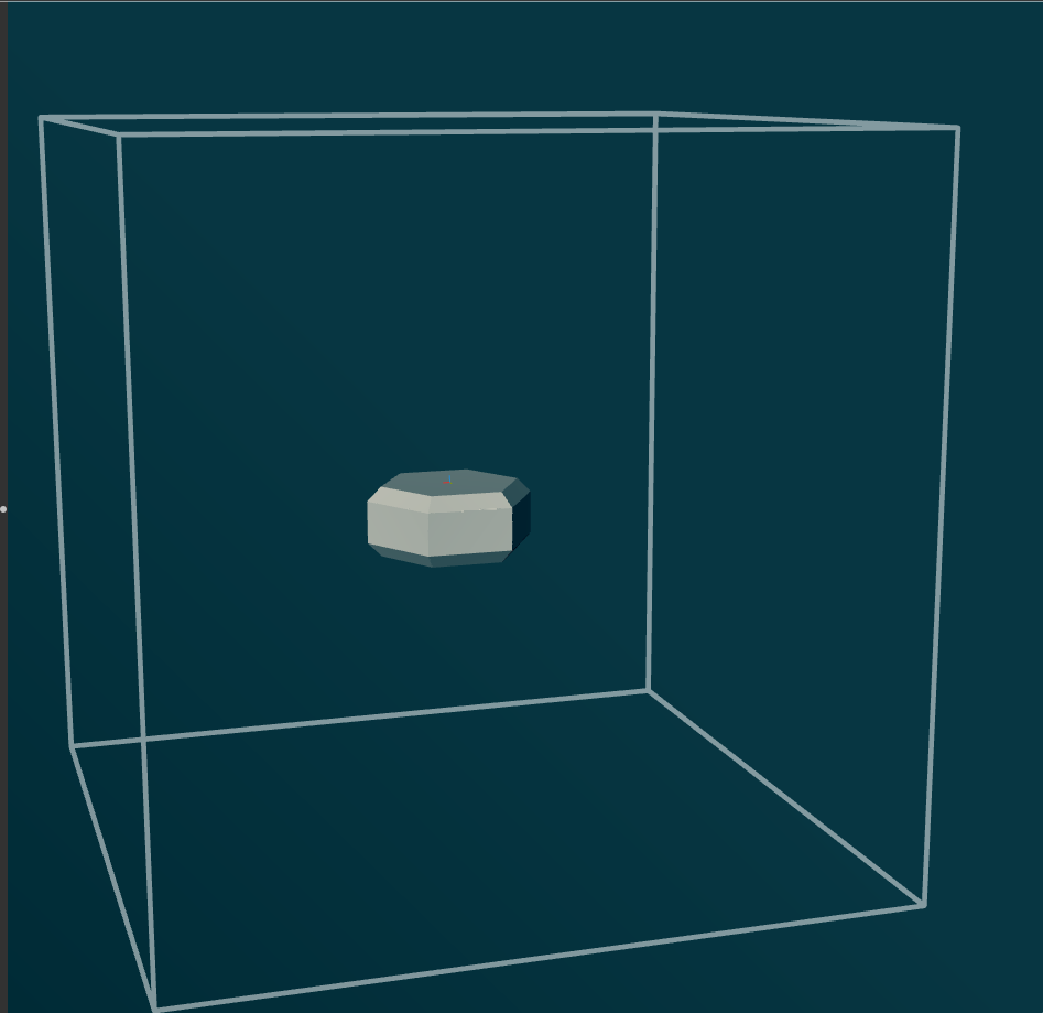
Note the two chamfers done using the symmetric z-inside coordinate.
Defining a thread
To do the thread, we compute the angle around the axis and the zpitch (z position relative to the thread crest). To make things nice and continuous, the z position is symmetric, going between 0 and pitch / 2.
For the simplest thread profile, we just subtract that position (multiplied by the thread angle factor) from the outer radius and we’re done.
(define-shape (thread x y z)
  (let* (;; Calculate the phase based on the x,y coordinates
         (phase (/ (atan x y) (* 2 pi)))

         ;; Position in thread pitch (0 to pitch/2 from crest to trough)
         (zpitch (abs (+ (modulo (+ z (* thread-pitch phase)) thread-pitch)
                         (* -0.5 thread-pitch))))

         ;; Radius from the center axis
         (r (sqrt (+ (* x x) (* y y))))

         ;; Thread radius at current position
         (r-thread (- (* 0.5 thread-d)
                      (* zpitch (tan (/ thread-angle 2))))))
    (- r r-thread)))
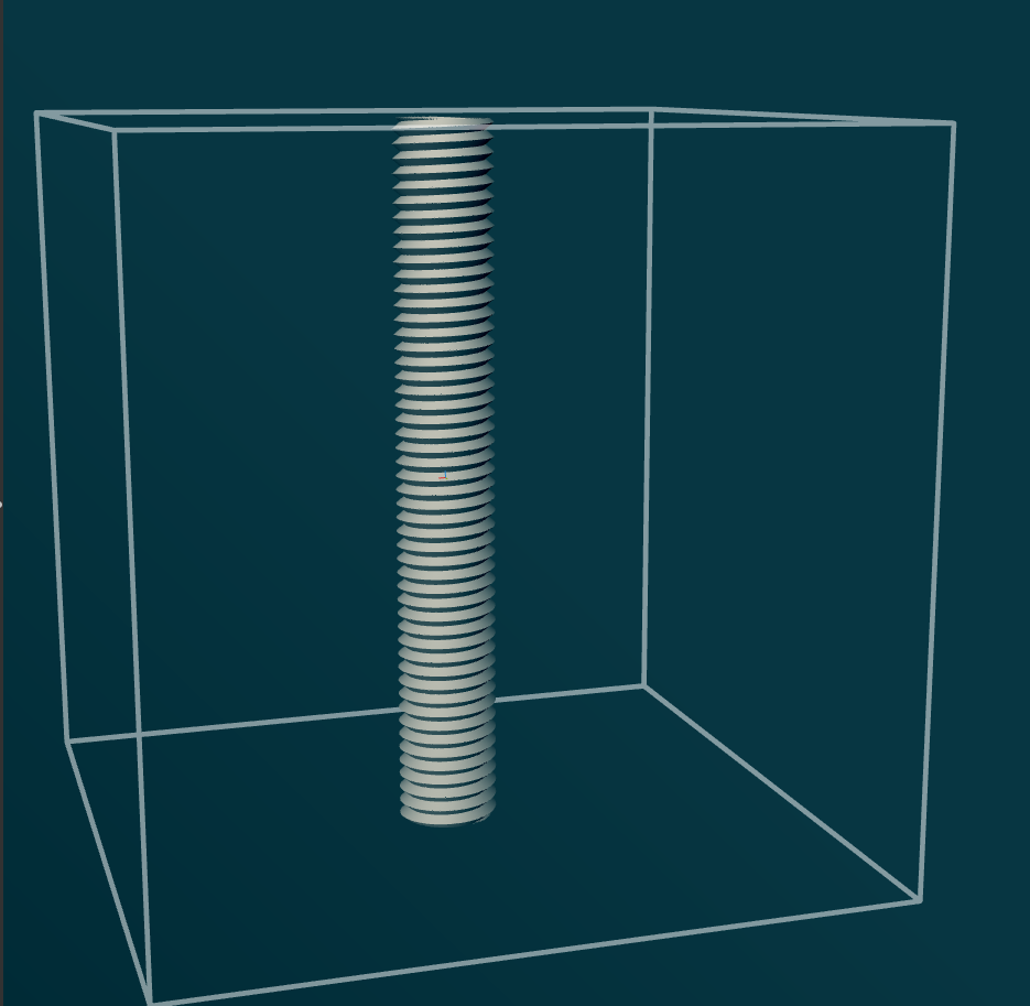
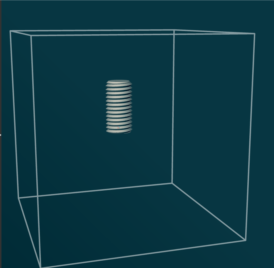
and cut it to length (the chamfer at top is important, otherwise screws are hard to insert)
(define-shape (cut-thread x y z)
  (let ((r (sqrt (+ (* x x) (* y y)))))
    (max
     (- -2 z)               ; Bottom cutoff
     thread                 ; Thread profile
     (+ (- thread-length) z) ; Top limit
     ;; Chamfer at the thread entry point
     (- (- r (* 0.5 thread-d))
        (- thread-length 1.5 z))
     )))
Combining the two
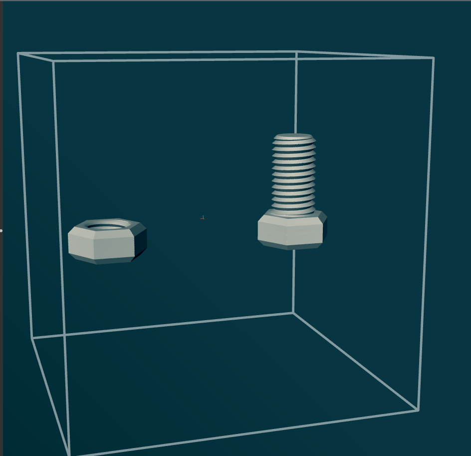
Here’s how we combine the hex nut shape with the threads in two different ways (nut and screw), with a blend:
;; nut
;; 0.1mm looser is just right on my 3D printer
;; to have the thread work nicely
(move (blend-difference hex (- thread 0.1) 1) [30 0 0])

;; screw
(move (blend hex cut-thread 1.5) [-30 0 0])
Adding a simple member
And something to screw together with the screws (need to print at least two of these :) )
;; Given two shapes, intersect them with a chamfered edge.
;; a and b are shapes, and c is a number (size of chamfer).
;;
;; The implementation of this function cracks me up :)
;;
;; (The input shapes a and b must have proper distance fields
;; though, for this to work properly)
(define (intersect-chamfer a b c)
  (max a b (+ a b c)))

(define holes
  (symmetric-y
   (- (array-xy (circle (* 0.5 14.5))
                10 10 [25 25]))))

(define-shape (member x y z)
  (intersect-chamfer
   (intersect-chamfer
    (- (abs z) 3)
    (- (rectangle-exact [-0 -25 0] [0 25 0]) 12)
    1)
   holes 1))

member
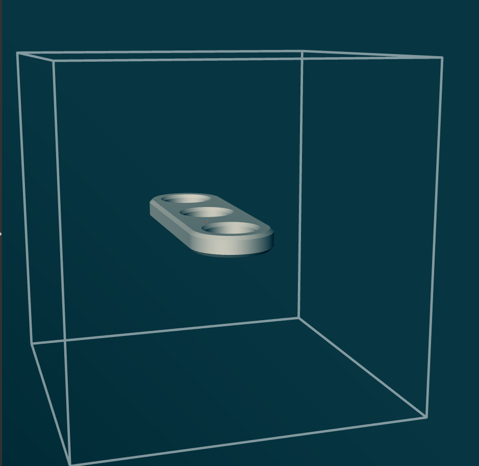
(Probably I’ll design these in Fusion in the future; the extra complexity of implicit modeling is so not worth it here)
Printing
Combining the above, we have the following model
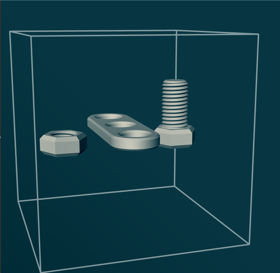
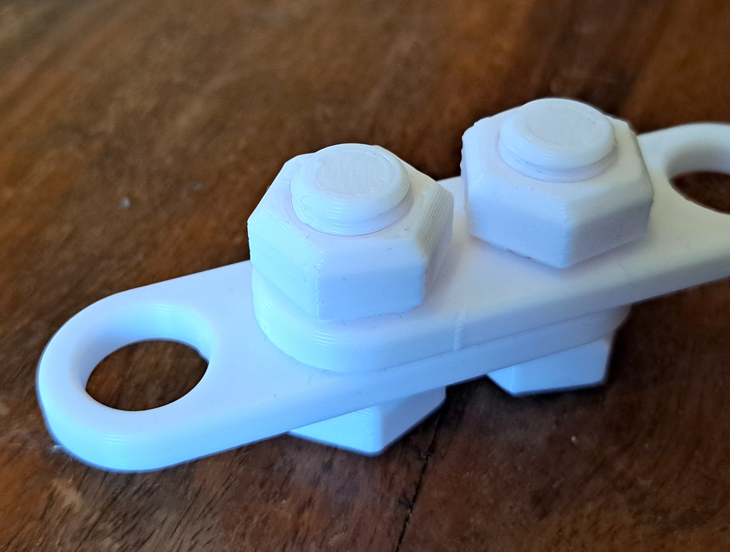
Exporting it as an STL file from libfive studio and printing it using PrusaSlicer was uneventful.

…and it actually works!
Thoughts
After this project, it’s more clear to me than ever why implicit modeling is only used in special circumstances. Even with a fast and polished tool like libfive, it takes a surprising amount of thinking to do simple things.
I guess it comes down to this: In a CAD program, you have the 3D object you are modeling right there in the window to operate on. In implicit modeling there’s always that extra step between coordinate systems and the object.
On the other hand, when you hit the limits of your CAD software, it’s really good to have implicit modeling available.
Future
It seems the author of libfive is looking at a different tack on implicit modeling. There are probably lots of interesting developments coming. It might even be that at some point I’ll take another look at doing implicit surfaces with Jax (don’t hold your breath :) ).
Anyway, libfive works today. It’s a useful tool to have in your back pocket.
Footnotes
Implicit blending
Implicit blending is its own can of worms: if all your objects have proper distance functions, blending works like a dream and you can have really nice shapes. However, if you (like us, with the thread) don’t, the blends will be what they will be. Also, unlike with CAD modeling, don’t expect to be able to be doing sequential ops: after blending, the blended object is no longer with a proper distance function. So better combine all object parts and holes in one go (not an original idea; I forget where I first saw this). Here, the blend looks passable.
AI disclaimer
I asked Claude to go over my scheme code and make it more idiomatic; mostly it reformatted the comments and reindented (I don’t have a scheme editing pipeline set up). Otherwise the is artisanal :)
License:
All code included in this post is licensed under the CC0 1.0 Universal (CC0 1.0) Public Domain Dedication. You can copy, modify, distribute and perform the work, even for commercial purposes, all without asking permission. Of course, attribution would be appreciated where possible.
Enjoy Reading This Article?
Here are some more articles you might like to read next: